LTMC CNC Busbar Machine Egypt

How a Busbar Bending Machine Works — Principles and Operation for Egyptian Workshops
Release time:
2026-11-13
Topic: How a busbar bending machine works — principles and operation for Egyptian workshops
Primary how-to source: Official LT CNC bend training (lessons 001–013)
Related models: LT / LTMC punch/cut/bend 3-in-1 303U-3-C / 503U-3-C / 803U-3-C
Quick answer
A busbar bending machine (or the bending station on a punch/cut/bend 3-in-1) forms copper or aluminum busbars to a target angle by hydraulic force driving a bend punch into a bend die, under CNC / PLC angle control. The physical cycle is clamp → bend → release; accuracy depends on die radius, thickness/width capacity, springback / angle compensation, and correct foot-switch timing. Official LT CNC training teaches the full operator path: lubrication and power → die install → CNC interface → manual / template / import programming → angle compensation → limited bending → die start position → foot switch → e-stop → maintenance. Egyptian workshops in Cairo, 10th of Ramadan or Alexandria should lock those steps into a shop SOP before releasing IEC 61439 cabinet bars.
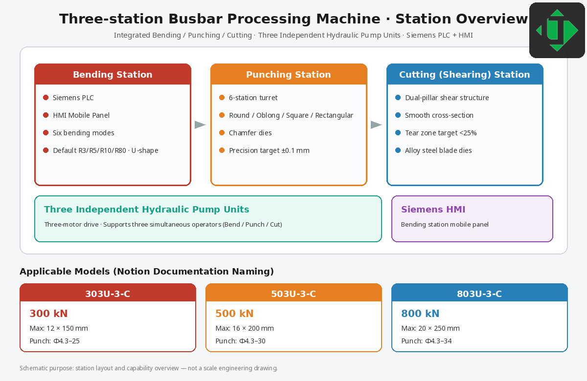
Three-station layout overview: bending, punching, cutting + three hydraulic pump units + Siemens HMI
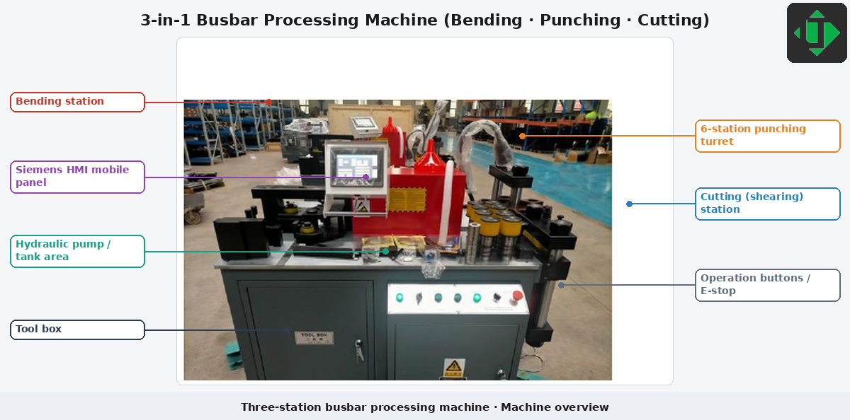
Machine overview with English callouts (stations, Siemens HMI, hydraulic area, controls)
1. Entity glossary
- Busbar bending machine / busbar bending station — hydraulic forming unit for flat Cu/Al bars
- Punch/cut/bend 3-in-1 — one frame with punching + cutting + bending (e.g. LT / LTMC 303U-3-C / 503U-3-C / 803U-3-C)
- Copper busbar / aluminum busbar — conductor bars for switchgear, transformers, distribution
- Bend die / bend punch — tooling pair that sets inside radius and bend geometry
- Flat bend vs edge (vertical) bend — bend across flat face vs across thickness edge
- CNC angle control / HMI / PLC — operator interface + controller that targets bend angle
- Hydraulic force — cylinder pressure (model class often 300 / 500 / 800 kN)
- Springback / angle compensation — material recovery after unload; program over-bend or table compensation
- Sequence: clamp → bend → release — safe mechanical cycle before measuring the part
- Limited bending mode — stroke-limit / position-limit bending for special tooling
- Foot switch — hands-free start of the bend cycle
- Die starting position (lower die / concave die) — home / approach reference for the lower die
- Tooling radii — common defaults R3, R5, R10, R80 or R50, plus U-shape
- Thickness / width capacity — max bar size the station can bend (confirm on OA)
2. Working principle (mechanism)
2.1 Force and tooling
- The operator seats the copper or aluminum busbar on the worktable against stops.
- The upper bend punch advances under hydraulic force into the lower bend die.
- Plastic deformation creates the bend; the inside radius follows the die/punch family.
- On unload, the bar springs back; the CNC applies angle compensation so the final angle matches the drawing.
- The actuator releases; the operator removes the bar, measures, and updates compensation if needed.
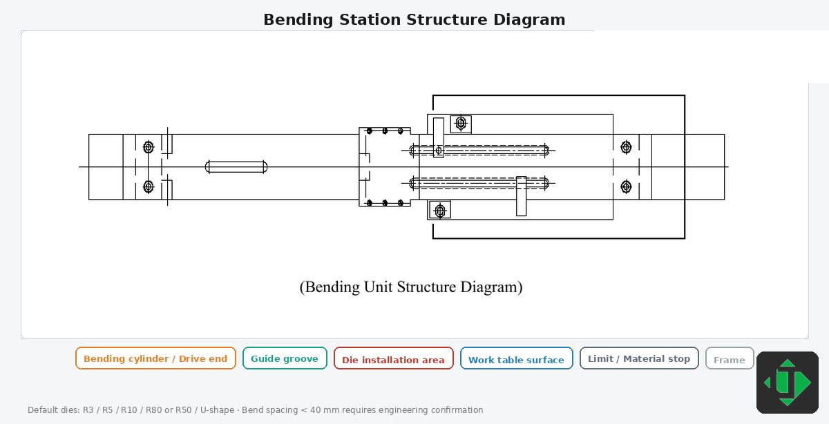
Bending station structure diagram (cylinder, guide, die mount, table, stops)
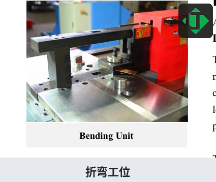
Bending station photo: worktable and bending die area
2.2 Control modes (LT CNC training map)
Official LT CNC lessons expose these programming / run modes operators in Egyptian shops must master:
| Mode / topic | Lesson | What it is for |
|---|---|---|
| Manual editing mode | 004 | Enter bend length / thickness / angle (and related parameters) by hand on the CNC |
| Template graphic editing mode | 005 | Build bends from graphic templates (L / Z / U-style patterns and similar shapes) |
| Data import mode | 006 | Import bend data from external files / host instead of typing every step |
| Angle compensation | 007 | Correct springback so measured angle = drawing angle |
| Limited bending mode | 008 | Bend by stroke / position limits when angle mode is not enough |
| Modify die starting position | 009 | Set lower-die (concave die) start / approach reference |
2.3 Flat bend vs edge bend; radius; capacity
- Flat bend: bar lies flat; punch forms the angle across the width.
- Edge (vertical) bend: bar is oriented for bending on the edge — capacity is lower than flat bend on the same model.
- Radius: choose R3 / R5 / R10 / R80 (or R50) / U-shape to match drawing and material; aluminum usually needs a larger minimum inside radius than copper.
- Close bends: if the distance between two bends is under ~40 mm, engineering must confirm tooling clearance.
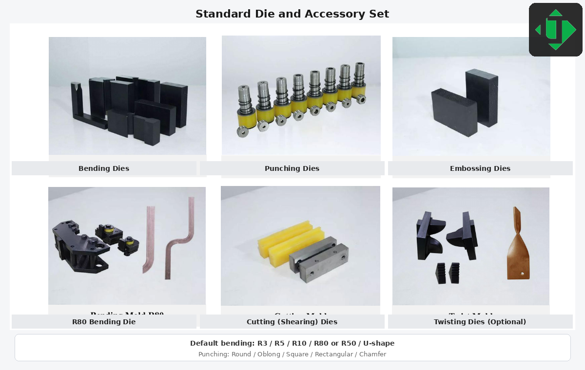
Standard die and accessory set with English labels (default radii and punch shapes)
3. HowTo — official LT CNC operation (lessons 001–013)
Follow this order. It is the official LT CNC operator path; use it as a written shop procedure. LT / LTMC can support Egyptian workshops with guidance, commissioning, operator training, spare parts, and remote support—this article does not embed training videos.
HowTo overview (workshop sequence)
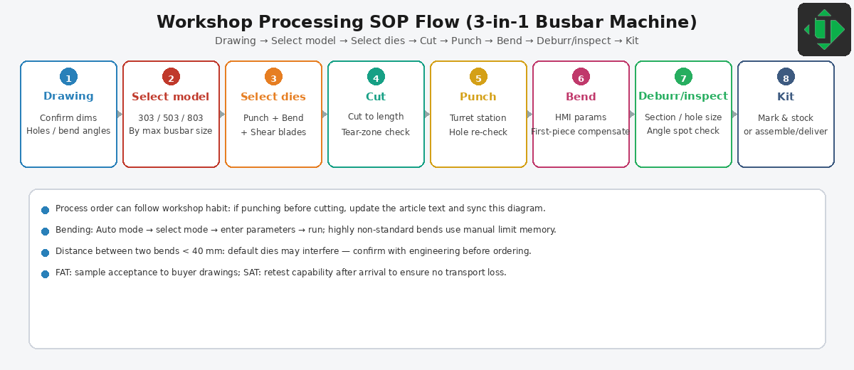
Workshop SOP flow: Drawing → Select model → Select dies → Cut → Punch → Bend → Deburr/inspect → Kit
Bend-station path (LT): lubricate and wire → install dies → power on CNC → program (manual / template / import) → compensate angle → (optional) limited bend + die start position → foot-switch run → e-stop drill → maintain.
Step 001 — Lubrication and power cord installation
Official LT CNC training 001 — lubrication and power cord installation. Follow the lesson order; this page is a written HowTo, not a video embed.
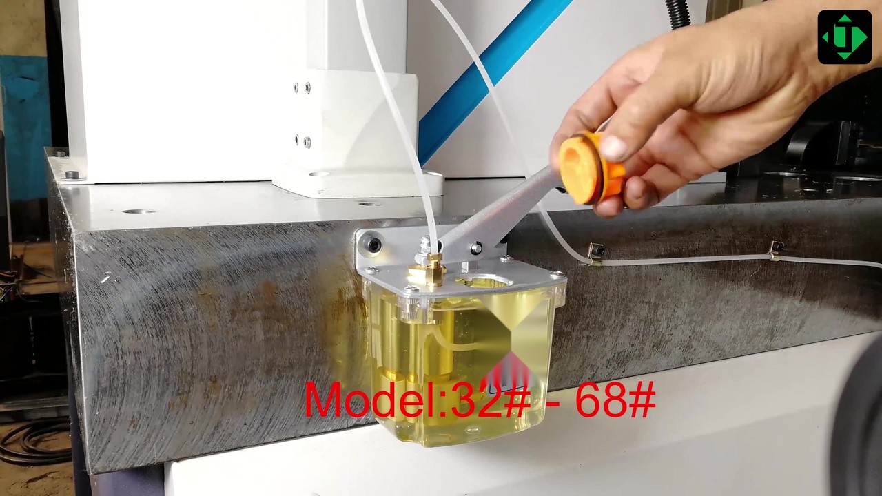
Official LT CNC training 001 — lubrication and power cord installation
- Confirm the machine is powered off and the main disconnect is locked if required by site rules.
- Fill / top up guide and friction points with the specified lubricant.
- Inspect for dry slides, exposed ram guides, and oil residue that indicates leaks.
- Connect the power cord to the matching industrial voltage receptacle (often 380 V / 50 Hz in Egyptian factories; confirm the nameplate).
- Verify earth / ground continuity and that the plug rating matches the machine nameplate.
- Route the cord so it cannot be pinched by forklifts or the foot switch.
Step 002 — Die set introduction and installation
Official LT CNC training 002 — die set introduction and installation. Follow the lesson order; this page is a written HowTo, not a video embed.
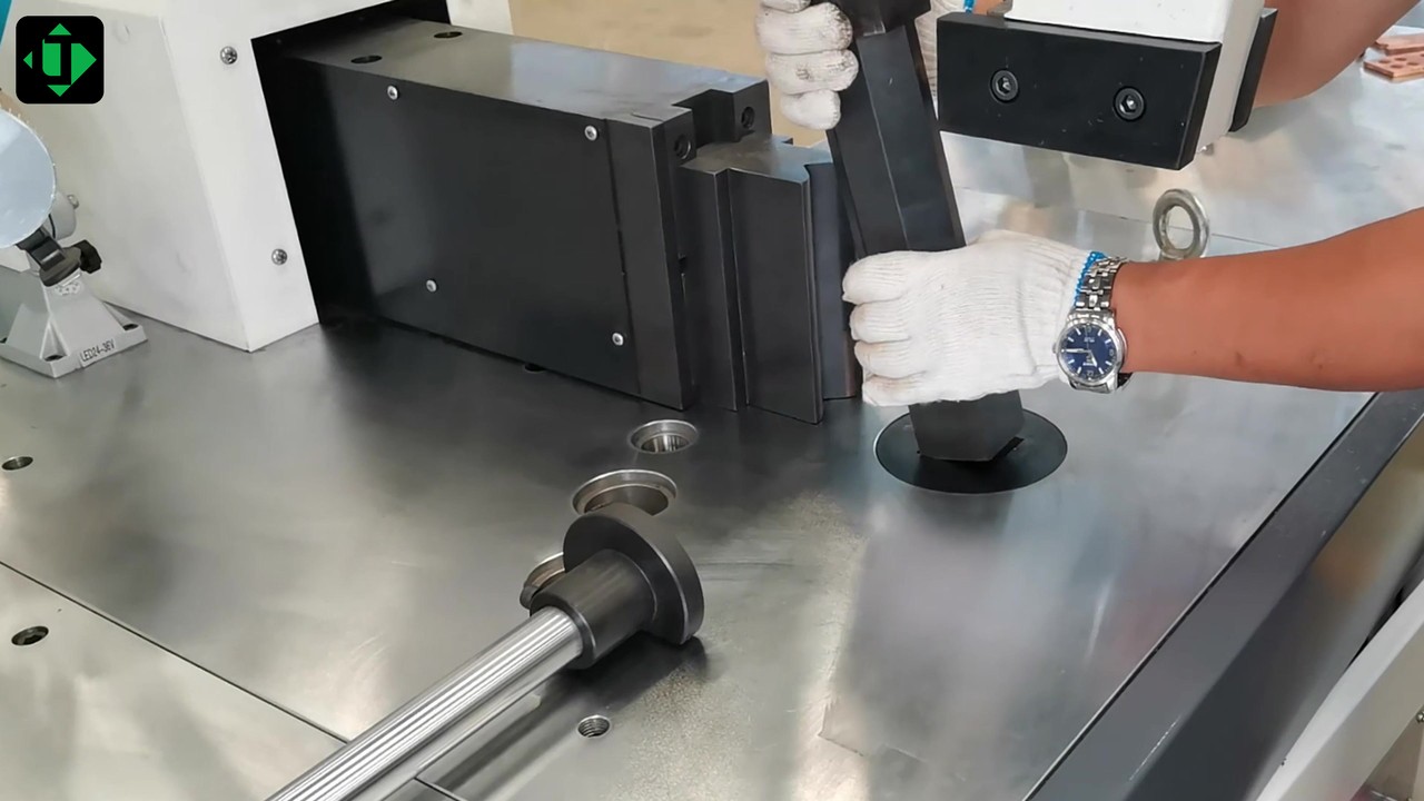
Official LT CNC training 002 — die set introduction and installation
- Identify the bend punch / bend die set for the job (radius family and U-shape if required).
- Clean seating faces; remove chips that would tilt the die.
- Install the lower (concave) die on the table / mount; lock fasteners to the specified torque.
- Install the upper punch; confirm alignment with the lower die centerline.
- Jog carefully (after power-on in Step 003) to verify clearance before production bars.
- For multi-bend parts, confirm the die package covers every radius on the drawing.
Step 003 — Power on and CNC interface
Official LT CNC training 003 — power on and CNC interface. Follow the lesson order; this page is a written HowTo, not a video embed.
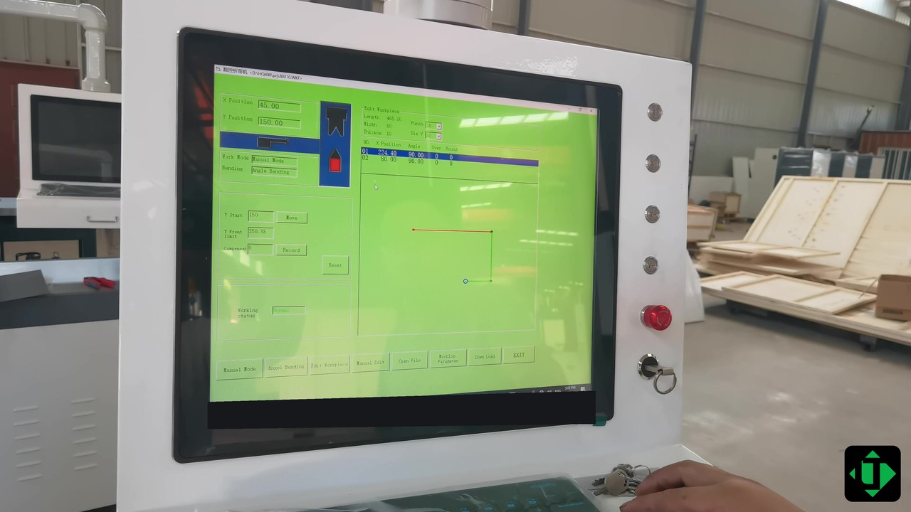
Official LT CNC training 003 — power on and CNC interface
- Switch on the main power.
- Wait for the CNC / HMI to boot to the home screen.
- Confirm language (as ordered) and that no alarm banner is active.
- Open the bending application / CNC interface.
- Check hydraulic ready state (motor / pump indicators) before jogging axes.
- Do not place hands in the die area while enabling motion.
Step 004 — Manual editing mode
Official LT CNC training 004 — manual editing mode. Follow the lesson order; this page is a written HowTo, not a video embed.
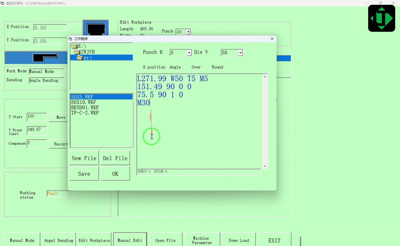
Official LT CNC training 004 — manual editing mode
- From the CNC menu, select Manual editing mode.
- Create or open a program for the current busbar part.
- Enter busbar parameters: length-related fields, thickness, material notes if the screen provides them.
- Enter the target bend angle (and bend sequence if multi-bend).
- Save the program; dry-review the step list on screen.
- Run a first-piece bend with the foot switch (Step 010), then measure and go to Angle Compensation (Step 007) if needed.
Step 005 — Template graphic editing mode
Official LT CNC training 005 — template graphic editing mode. Follow the lesson order; this page is a written HowTo, not a video embed.
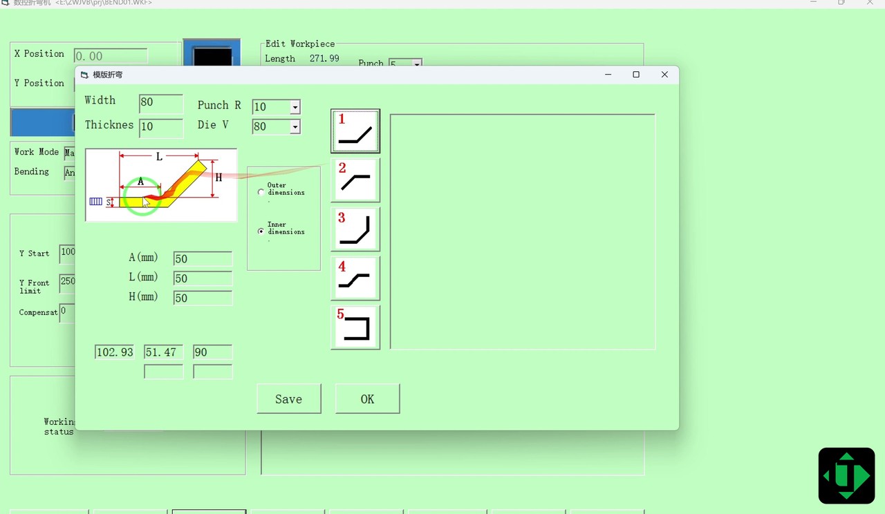
Official LT CNC training 005 — template graphic editing mode
- Open Template graphic editing mode on the CNC.
- Select the graphic template that matches the part family (e.g. L / Z / U-style patterns).
- Fill segment lengths and angles for each bend in the template.
- Preview the graphic; correct any segment that conflicts with die width or min flange.
- Save as a named program for repeat jobs — useful for recurring Egyptian panel shapes.
- Prefer templates for recurring panel shapes; use Manual (004) for one-off odd bends.
Step 006 — Data import mode
Official LT CNC training 006 — data import mode. Follow the lesson order; this page is a written HowTo, not a video embed.
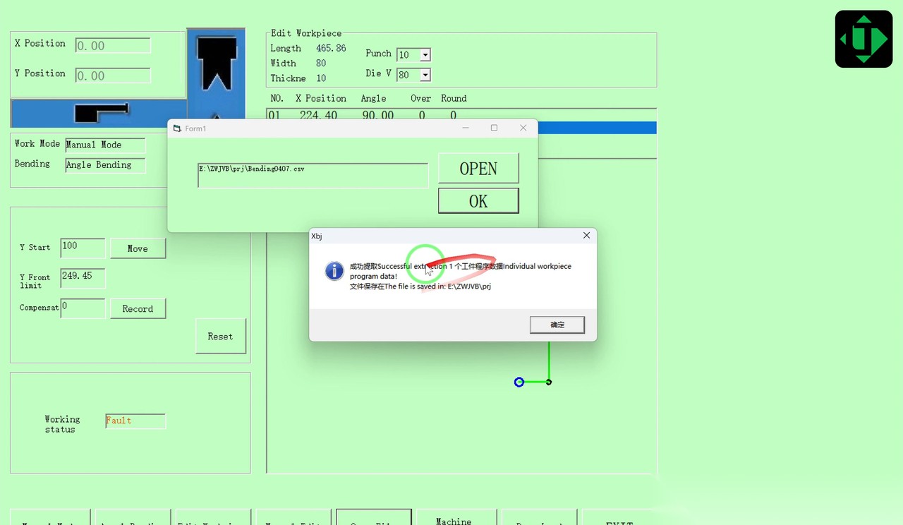
Official LT CNC training 006 — data import mode
- Prepare the bend data file on the media / path used by the controller (USB or network as applicable).
- Open Data import mode on the CNC.
- Browse to the file; import into the bend program list.
- Verify imported lengths / angles against the drawing before running.
- Store a shop copy of the proven file for the next batch.
- After import, still run a measured first piece — import does not remove springback.
Step 007 — Angle compensation (springback)
Official LT CNC training 007 — angle compensation. Follow the lesson order; this page is a written HowTo, not a video embed.
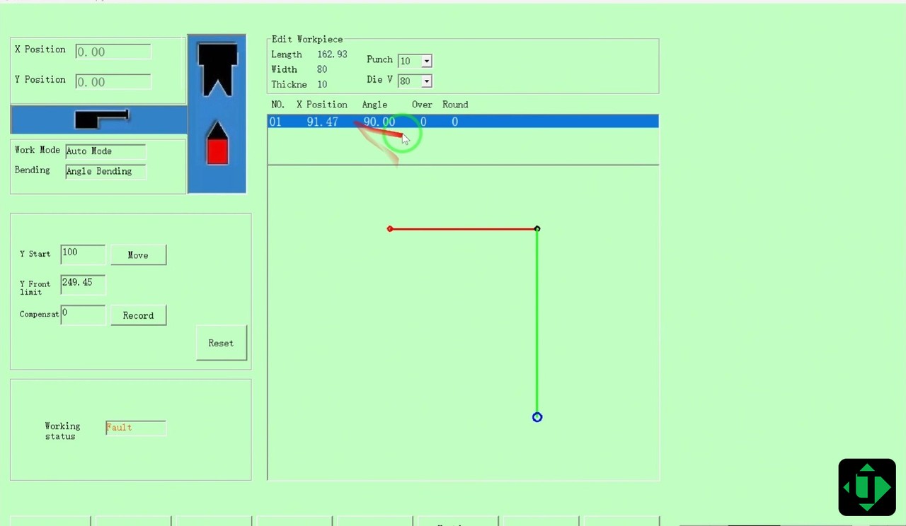
Official LT CNC training 007 — angle compensation
- Bend a trial piece with the programmed target angle.
- Measure the actual angle with a protractor / digital angle gauge on the cooled bar.
- Open Angle compensation on the CNC.
- Enter the compensation so that programmed + compensation → drawing angle after springback.
- Save compensation per material (copper vs aluminum tables must stay separate).
- Re-run and confirm; lock the recipe for the batch.
Why it matters: aluminum typically needs larger springback compensation and a larger minimum inside radius than copper. Never copy a copper program onto aluminum without a new trial bend. A drifted released angle will not fit an approved IEC 61439 cabinet.
Step 008 — Limited bending mode
Official LT CNC training 008 — limited bending mode. Follow the lesson order; this page is a written HowTo, not a video embed.
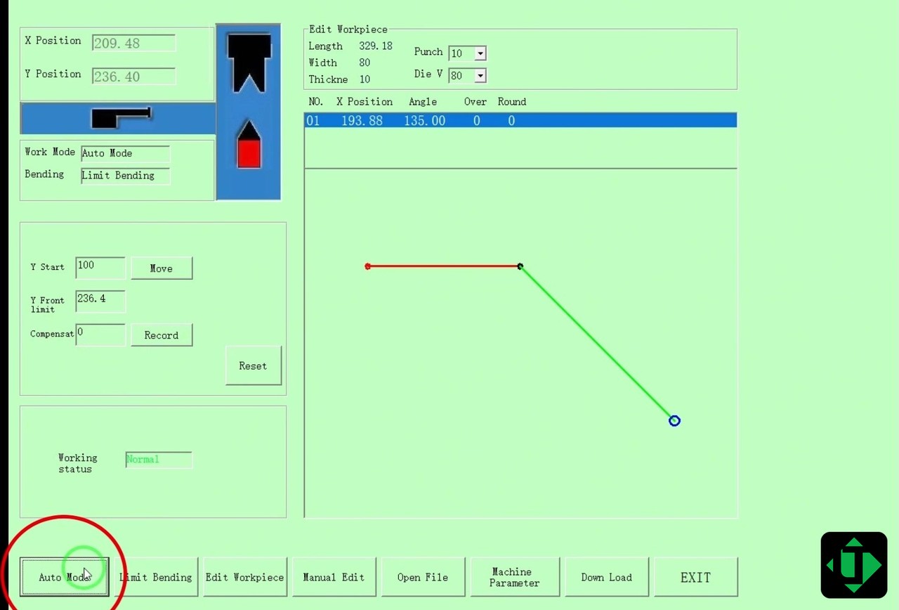
Official LT CNC training 008 — limited bending mode
- Use Limited bending mode when the job is controlled by stroke / position limits rather than a simple angle recipe (custom dies, unconventional shapes).
- Set the forward limit and reverse / return limit as trained.
- Jog the first piece carefully to prove limits before continuous production.
- After the first debug, repeat bends without re-teaching if the tooling and thickness are unchanged.
- Document limit values on the traveler for the next shift.
Step 009 — Modify die starting position
Official LT CNC training 009 — modify die starting position. Follow the lesson order; this page is a written HowTo, not a video embed.
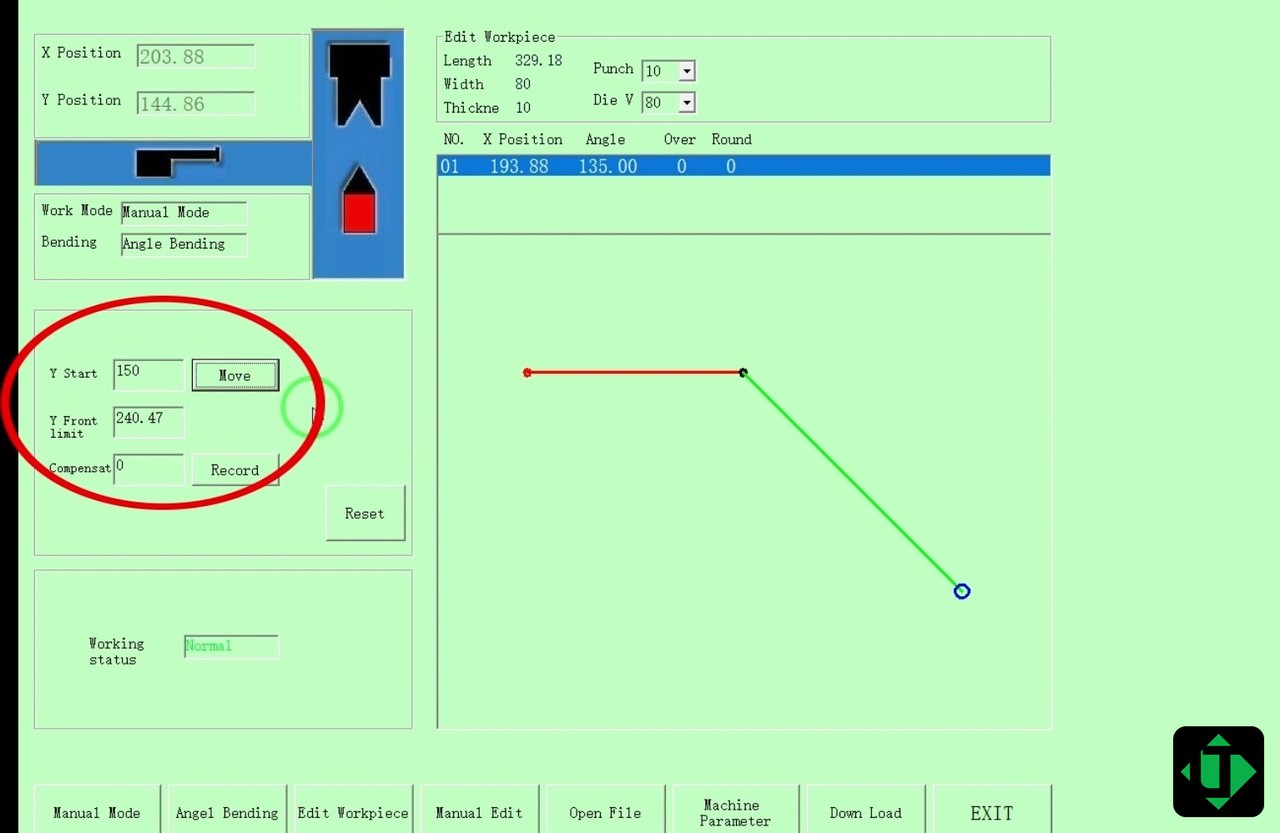
Official LT CNC training 009 — modify die starting position
- Open the function to modify the concave (lower) die starting position.
- Jog or enter the new start / approach reference.
- Confirm the punch / die do not collide at the new start.
- Save; re-check first-piece angle after changing start position (geometry of the bend can shift).
- Reset to the factory / known-good start when changing back to standard dies.
Step 010 — Foot switch operation (clamp → bend → release)
Official LT CNC training 010 — foot switch operation. Follow the lesson order; this page is a written HowTo, not a video embed.
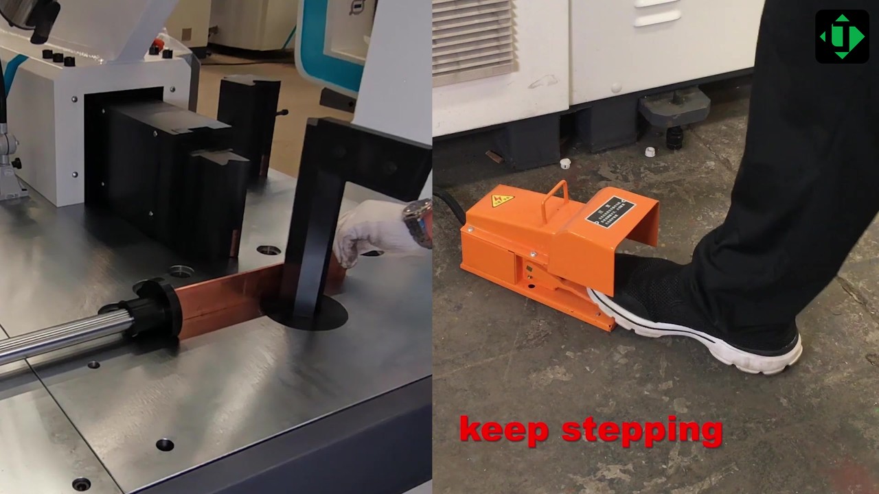
Official LT CNC training 010 — foot switch operation
- Place the busbar against stops; hands clear of the die.
- Confirm program mode (004 / 005 / 006 / 008) and compensation (007) are ready.
- Press the foot switch to start the cycle: the machine clamps / approaches → bends → releases per the active program.
- Keep both hands outside the hazard zone for the entire stroke.
- Remove the bar only after the ram has returned and motion has stopped.
- Measure; if out of tolerance, return to Step 007 before the next piece.
Step 011 — Emergency stop and recovery
Official LT CNC training 011 — emergency stop and recovery. Follow the lesson order; this page is a written HowTo, not a video embed.
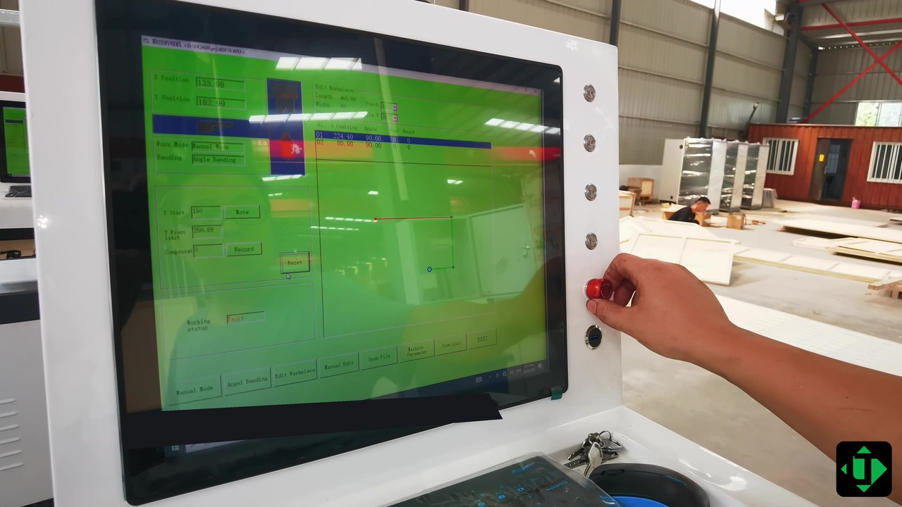
Official LT CNC training 011 — emergency stop and recovery
- Hit Emergency Stop immediately on any personnel or tooling hazard.
- Wait for all motion to cease; do not reach into the dies yet.
- Follow the trained recovery: reset E-stop, clear alarms, re-enable hydraulics.
- Inspect the bar and dies for damage before re-running.
- Re-home or re-establish die start position (009) if the stop interrupted mid-stroke.
- Document the event on the shift log.
Step 012 — Foot switch errors and solutions
Official LT CNC training 012 — foot switch errors and solutions. Follow the lesson order; this page is a written HowTo, not a video embed.
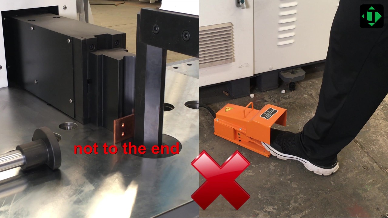
Official LT CNC training 012 — foot switch errors and solutions
- If the cycle does not start: check E-stop state, mode selection, and foot-switch cable.
- If the cycle aborts mid-bend: note the alarm code; recover per Step 011.
- If double-trigger / unintended motion occurs: stop; inspect the pedal for sticking or debris.
- Apply the corrective actions from official LT training before returning to production.
- Retrain operators who skip the “hands clear” rule.
Step 013 — Maintenance
Official LT CNC training 013 — maintenance. Follow the lesson order; this page is a written HowTo, not a video embed.
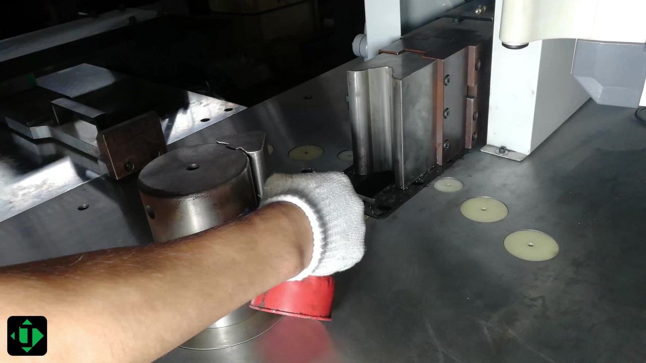
Official LT CNC training 013 — maintenance
- Power down and lock out before opening guards or changing major tooling.
- Relubricate guides on the specified interval; check hydraulic oil level / condition.
- Inspect punch/die edges for galling; dress or replace before angle drift grows.
- Keep copper and aluminum practices separate if oxide / smear is an issue on shared dies.
- Verify foot switch and E-stop function at the start of each shift.
- Record hours, oil changes, and die life for TCO.
4. Safety checklist
- PPE: safety glasses, safety shoes; no gloves that can catch in dies if site policy forbids them at the punch point.
- Never exceed published width × thickness for flat or edge bend.
- Lock out before die changes (002) and major maintenance (013).
- Hands clear during foot-switch cycles (010); know E-stop recovery (011).
- Keep compensation tables material-specific (007).
5. Capacity snapshot (3-in-1 context — confirm on OA)
| Entity | 303U-3-C | 503U-3-C | 803U-3-C |
|---|---|---|---|
| Nominal force (kN) | 300 | 500 | 800 |
| Max horizontal bend W×T (mm) | 150×12 | 200×16 | 250×20 |
| Max vertical bend (mm) | 10×100 | 12×120 | 12×120 |
| Default bend dies | R3 / R5 / R10 / R80 or R50 / U-shape | same family | same family |
| Published bend precision / repeat | about ±1° / ±0.5° | about ±1° / ±0.5° | about ±1° / ±0.5° |
See also CNC busbar bending machine and 3-in-1 busbar machine.
6. FAQ
What is a busbar bending machine?
A busbar bending machine (or bending station) uses hydraulic force and a bend punch/die under CNC angle control to form copper or aluminum busbars for switchgear and power distribution.
How does the bend cycle work?
The standard sequence is clamp → bend → release, usually started with a foot switch, then the part is measured and angle compensation corrects springback.
What is the official LT CNC training order?
Lubrication and power (001) → die install (002) → power on CNC (003) → manual (004) / template (005) / import (006) → angle compensation (007) → limited bending (008) → die start position (009) → foot switch (010) → e-stop (011) → foot-switch errors (012) → maintenance (013).
Manual vs template vs import mode?
Manual types parameters; template graphic builds from shape templates; data import loads external bend data — all still need first-piece measurement.
Why is angle compensation required?
Because springback moves the free angle after unload; copper and aluminum need separate compensation tables.
What is limited bending mode?
A stroke / position limit method for unconventional or highly repeatable tooling setups when a simple angle program is not enough.
Flat bend vs edge bend?
Flat bend uses the bar’s flat face; edge (vertical) bend bends on the edge and usually has a lower size limit on the same machine.
Which dies are commonly supplied?
R3, R5, R10, R80 or R50, and U-shape, plus options such as emboss / twist on some packages — confirm on the order list.
How do 3-in-1 models relate?
On LT / LTMC 303U-3-C / 503U-3-C / 803U-3-C, bending is one of three hydraulic stations (with punch and cut). Size by max width×thickness and hardest bend family.
How can Egyptian workshops get operator training?
LT / LTMC provides guidance, commissioning, operator training, spare parts, and remote support. Contact egyptbusbar.com/contact — this page does not embed training videos.
7. Closing for buyers and RFQs
A busbar bending machine combines hydraulic force, bend die/punch tooling, CNC / HMI / PLC angle control, and a safe clamp → bend → release cycle operated by foot switch, with angle compensation for copper vs aluminum springback. Master the official LT CNC modules 001–013 before production; when the bend station sits on a punch/cut/bend 3-in-1, also confirm 303U-3-C / 503U-3-C / 803U-3-C width×thickness, vertical-bend limits, and die package on the order acknowledgment.
Next step for Egyptian workshops
Share representative busbar drawings, copper or aluminum grade and temper (for example Cu-ETP / C11000 where specified), max width × thickness, and FAT sample requirements. LT / LTMC can support Egyptian panel and transformer shops with technical guidance, commissioning, operator training, spare parts, and remote support. Product pages and contact:
- 3-in-1 busbar machine
- CNC busbar bending machine
- CNC busbar punching and cutting machine
- egyptbusbar.com · Contact
Where a public page and the order acknowledgment differ, treat the OA and FAT samples as the source of truth.
Latest News
How a Busbar Bending Machine Works — Principles and Operation for Egyptian Workshops
How a busbar bending machine works in Egyptian workshops: principles, springback, flat vs edge bends, and official LT CNC operation steps 001–013 on 3-in-1 bend stations 303U-3-C /...
2026-11-13
Three-Station Busbar Machine Technical Guide for Egyptian Factories — LT 303/503/803
Technical guide to three-station (3-in-1) busbar machines for Egyptian factories: punch, cut and bend on LT 303U-3-C / 503U-3-C / 803U-3-C, with model cards, station diagrams, RFQ ...
2026-11-10
What Is a Busbar Machine? Cutting, Punching and Bending for Egyptian Switchgear
A busbar machine cuts, punches and bends copper or aluminum busbars for Egyptian switchgear. Learn how 3-in-1 stations work and how to choose LT 303U-3-C / 503U-3-C / 803U-3-C.
2026-11-10
Busbar Punching Guide for Egyptian Panel Shops — Hole Accuracy, Dies and Positioning
Busbar punching quality in Egyptian panel shops is finished hole position from the datum, size, burr and edge distance. Match turret dies and clearance on LTMC 303U-3-C / 503U-3-C ...
2026-11-10
How to Use a Busbar Bending Machine in Egyptian Switchgear Production
Production bending in Egyptian switchgear shops needs locked recipes, tooling and first/mid/last checks so released angles stay stable across shifts on LT 303U-3-C / 503U-3-C / 803...
2026-11-10
What Is a Busbar Bending Machine and How Does It Work in Egyptian Workshops?
A busbar bending machine forms copper or aluminum bars to drawing angles for Egyptian workshops. Judge released angle, radius and surface—not tonnage alone—on LTMC 3-in-1 bend stat...
2026-11-10
LTMC CNC Busbar Machine Egypt
Professional CNC Busbar Machine & Related Equipment Manufacturer.
Company Strength
Adequate Inventory
Fast Shipping
Our Products
CONTACT US
Address: No.9566 Jingshi Rd.Jinan City , Shandong , China


© COPYRIGHT 2025 LTMC CNC Busbar Machine Egypt

Contact Us
Our passion is to bring your ideas to life. Work with our design team to create a one-of-a-kind custom finish or cladding system to create a truly unique space. Together we can make your story stand out. If you need something to request a sample, request pricing, or request a demo, please fill out the contact form below. Explain your request in as much detail as you can and a representative will contact you within 1 business day.